Celica Headlights (W.I.P)

TLDR
One of the pop-up headlights was not deploying or retracting due to fried logic in the RTR Control Unit (a proprietary Toyota chip). Temporary manual control was achieved (by the use of a bypass momentary switch). A programmable ATtiny microcontroller is proposed as a permanent fix.
Problem
One of the pop-up headlights is not deploying or retracting. The cause was determined to be fried logic in the RTR Unit (Toyota proprietary chip). This car is equipped with flip-up headlights. It utilizes a retraction mechanism consisting of headlight motors, motor relays, and the RTR Control Unit.
Temporary Solution
Removed relay #2 and connected a momentary pushbutton switch between the N.O. (normally open) trace on the PCB and a steady supply of 12V. This setup restored motor functionality, enabling manual control. An unexpected but enjoyable side effect of this workaround is the ability to make the car “wink” by operating the headlights independently. This happy accident has added a sense of fun and character to the car. It not only brings me joy but also puts smiles on the faces of passing motorists and pedestrians. This little quirk has made the car feel even more special and unique. 😄 While the current solution is functional and entertaining, the ultimate goal remains restoring automated factory-like control.
Initial Investigation
Uncovered a wiring diagram from the internet to gain intuition on how the system functions and help identify which wires connect to what component and for what purpose. Checked the RTR fuse in the engine bay fuse box, a single 30A fuse powering both motors. Since one motor received power, the fuse was ruled out as the issue. Searched for the RTR relay in the engine bay but found none. Located the headlight relay and verified it worked since both headlights lit up.
Testing the Faulty Motor
A multimeter confirmed the faulty motor did not receive power. Using a homemade power probe, I probed the working motor’s wires to identify ground and power connections. Verified the wiring diagram: the thick black/white striped cable was ground. At the faulty motor, probed the thick wire with the power probe and connected it to +12V. The motor worked. This confirmed the motor works but does not receive power. Possible scenarios: Severed wires or wires with increased resistance due to wear, humidity, or other factors. Faulty internal motor position switch. Faulty RTR Control Unit.
Narrowing Down the Problem
Removed the dash and located the RTR Control Unit below the CD player. Unplugged its connector and tested for continuity with a multimeter. Wires were fine, ruling out severed or degraded wiring (Scenario #1). Tested the internal motor switch for resistance. Values matched the functioning motor, making Scenario #2 improbable. Disassembled the RTR Control Unit. Checked the relays controlling the motors, desoldered, and tested the resistance of the relays’ switch and coil sides. Relays showed expected values (continuity on the switch side, and proper resistance on the coil), ruling them out as the issue. Concluded that the Toyota proprietary logic IC responsible for switching relay #2 was partially fried (after checking the diodes, and various capacitors on the board of course).
Permanent Solution Proposal
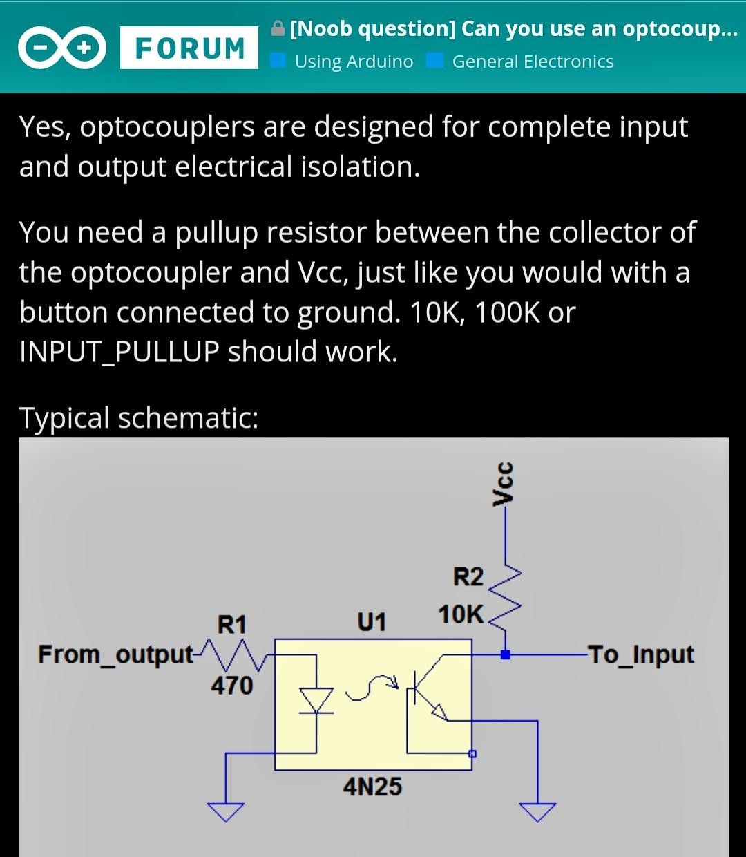
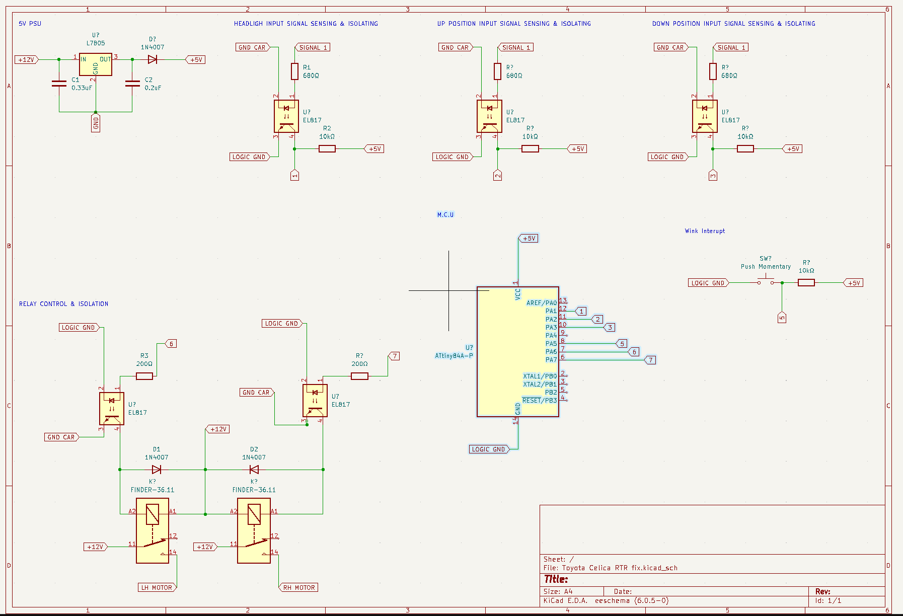
The goal is to restore factory-like headlight control using a programmable ATtiny microcontroller and optocouplers. Probed wires to find signals for headlight extension/retraction triggers. Used EL817 optocouplers as ATtiny input controllers (to effectively isolate and therefore protect both the microcontroller and the car from mulfuntions). Configuration: input with a 12V signal and 680Ω current-limiting resistor; output with the transistor side in pull-up configuration using a 1k–10k resistor.
Below there’s a picture of similar diagram from the Arduino Forum:

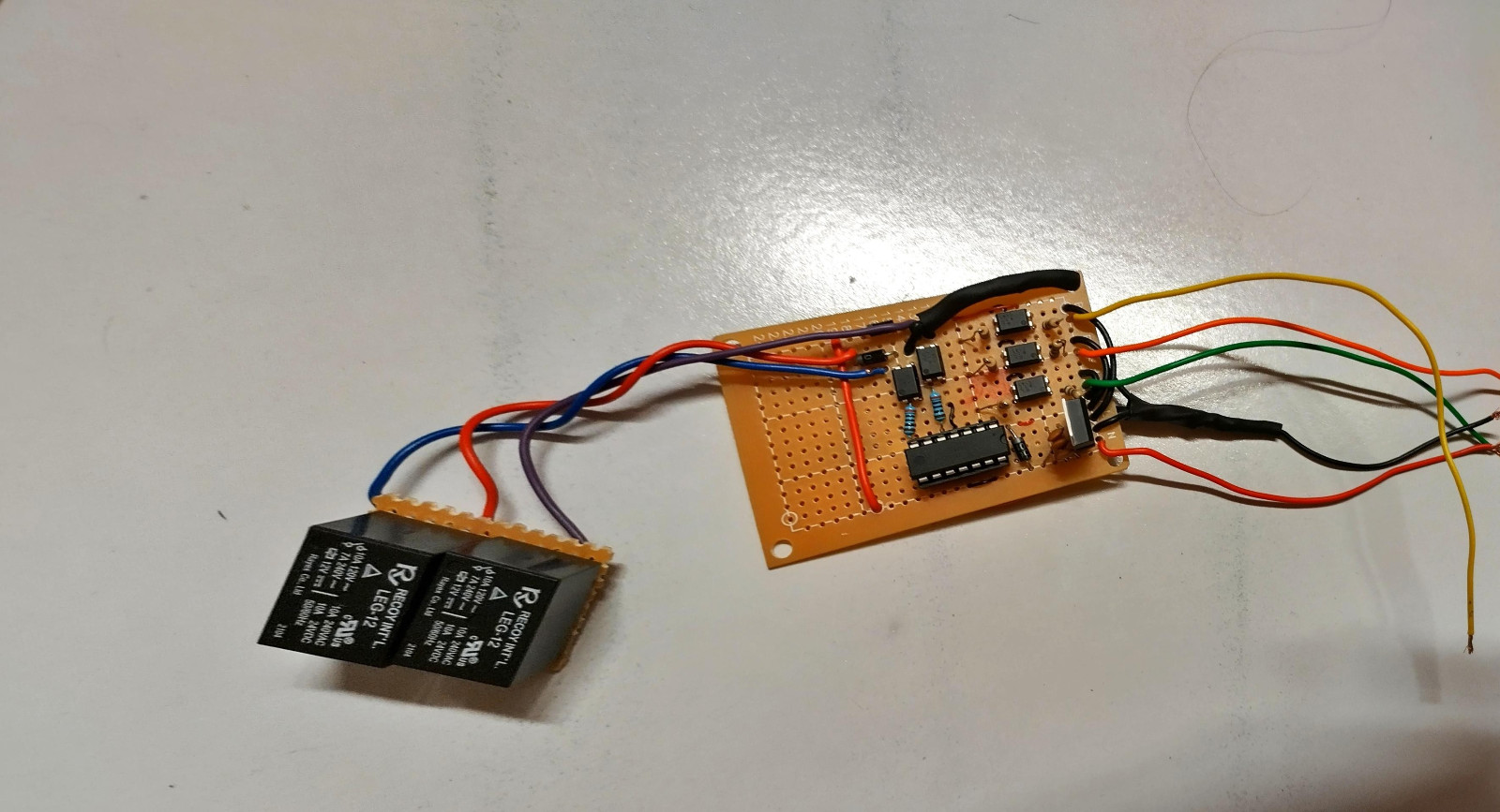
Added two more EL817 optocouplers, two relays, and flyback diodes to safely control motor motion with the ATtiny. Program logic included determining necessary conditions for motor rotation, creating a table of inputs (signals) and outputs (motor rotation states), and writing code with two if statements containing conditions for motor rotation. Added wink functionality using millis() for multitasking and an interrupt button.
You might wander what about the vehicle wiring? How is he going to connect this board to the vehicle. I used a multimeter and my diy power probe to figure out what each wire connects in the connector of the original unit. Common sense is a usefull tool too, for example the the tick wires must be the motor connection. Also another clue is that the thick wires are connected to the output relays on the board.

Challenges Encountered
The faulty motor lagged behind the other. Attempted to drive both motors directly from the custom PCB but discovered up/down position relies on the RTR Control Unit. Tried to emulate the motor with a resistor between the RTR relay side and ground to complete the logic circuit. Measured motor resistance between green and white/black wires to find the correct resistor value. However resistor emulation did not work. Tested different program versions but encountered issues such as desynchronization, continuous movement, and getting stuck in a constant loop of retractind/deploying the headlights.
Next Steps
Tweak the program to address these issues and finalize a reliable solution for factory-like functionality.
New Idea
I’ve been trying different versions of code and up to this point I haven’t got it to work properly (either didn’t work, was out of synch, kept moving while stuck in a loop). I will have to tweak the program as well to reflect these changes. I had a new idea! I don’t have an oscilloscope to see the signals the RTR is producing (I also do not know how to use one yet). However, I can remove the position wires from the RTR PCB and connect to my custom one. The plan is to connect the common, Up, and Down cables to the microcontroller’s IO and configure them as output, input, and input respectively. The idea is that common can be set to high on startup, then if a high signal is detected on the up cable the headlight is up, if in the down it’s down, else it’s in between. As you can tell, I will have to tweak the logic considerably and possibly add debouncing capacitors (to avoid accidental triggers).
Custom Board Schematic

