Celica Headlights

TL;DR
One of our Celica’s pop-up headlights stopped deploying and retracting. The motor still worked, the wiring was fine, and the relays measured fine. The proprietary logic IC in Toyota’s RTR Control Unit was half-fried.
I bypassed relay #2 with a momentary switch so I can run that motor by hand. As a byproduct, I can now make the car wink, to the amazement of bystanders ;)
That’s a temporary solution. The long-term plan is a programmable ATtiny board with optocouplers that restores factory-like automatic control and keeps the wink as a feature. Still working on the sync.
Stuck up (or down)
This Celica has flip-up headlights: a motor on each side, relays to drive them, and an RTR Control Unit that decides when each lamp goes up or down. One day one side just stopped listening. Lights switch on and that lamp stays put, either up or down depending on where it last stopped. I wanted both sides moving again without hunting down a replacement RTR.
The wink workaround
I needed something usable while I figured out the real fault. I removed relay #2 from the RTR board and jumped a momentary pushbutton between the N.O. (normally open) trace and a steady 12 V supply. Hold the button and the motor runs; let go and it stops. Crude, but it put the headlight back under my control.
Then I noticed the two lamps no longer have to move as a pair. Hold the bypass on one side and leave the other alone, and the car winks. I do it at lights, people notice, and some of them wave. It’s dumb and I like it a lot.
The button is still temporary. I want automatic, factory-like motion again, but the wink is staying.
Ruling things out
I started the way you usually do: find a wiring diagram online and learn which wire does what before you start poking live circuits. The RTR fuse in the engine bay is a single 30 A fuse for both motors. One motor still moved, so the fuse was fine. I hunted for an “RTR relay” in the bay and never found one. The headlight relay that actually lights the bulbs was fine too (both lamps lit when they should).
At the dead motor, the multimeter showed no power arriving. I used a homemade power probe on the working motor to map which thick wire was ground and which was +12 V. The diagram checked out: thick black/white striped cable is ground. On the dead side I probed the thick wire and fed it +12 V. The motor ran.
So the motor itself was healthy. Power just never got there in normal use. That left three possibilities:
- Severed or high-resistance wiring (age, humidity, chafe)
- A failed internal position switch inside the motor
- A dead or half-dead RTR Control Unit
I pulled the dash and found the RTR tucked under the CD player. Unplugged the connector and continuity-checked the harness with a multimeter. Wires were good, so scenario 1 was out. Resistance on the motor’s internal switch matched the working side, so scenario 2 looked unlikely.
Then I opened the RTR itself. Desoldered the motor relays and measured switch and coil sides. Continuity where it should be, coil resistance where it should be. Relays were fine. Caps and diodes on the board looked and measured fine too.
What remained was the Toyota proprietary logic IC that switches relay #2. That chip was partially fried.
Building a stand-in
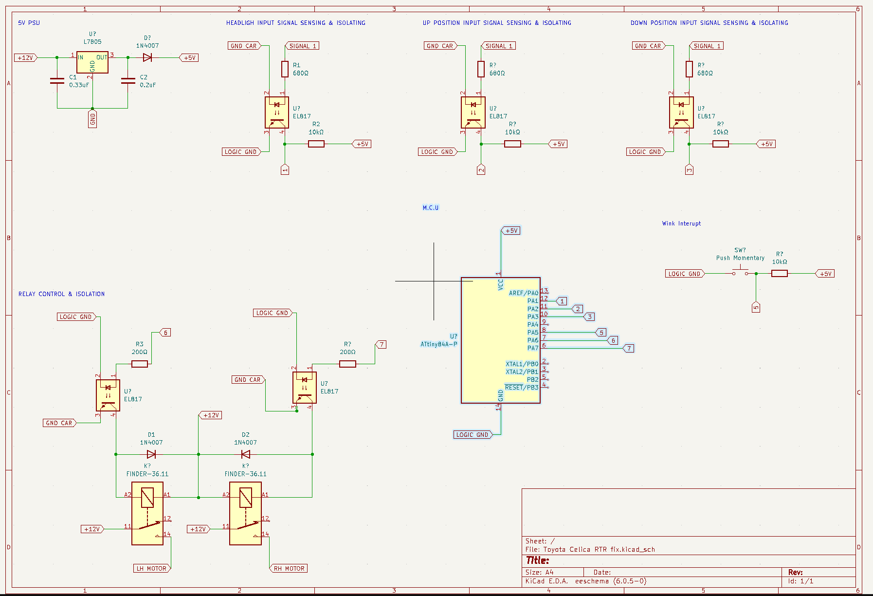
Replacement RTRs aren’t easy to find, and I wanted something I could program and repair anyway. An ATtiny plus optocouplers: listen to the car’s existing triggers, drive the motors safely, and keep the wink on purpose.
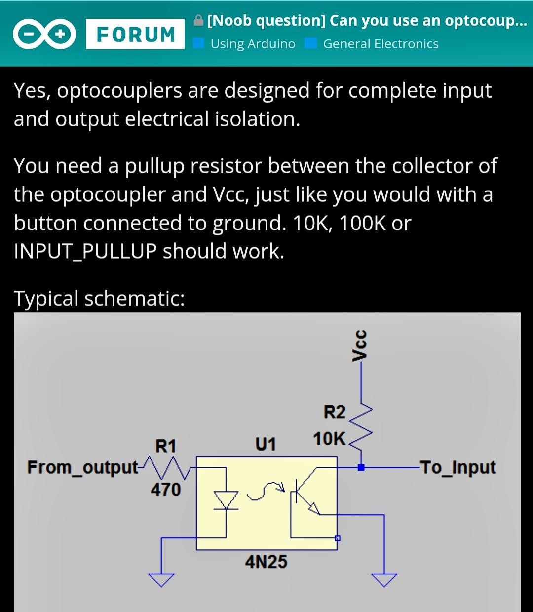
I probed for the signals that mean “extend” and “retract.” For inputs I used EL817 optocouplers so the microcontroller and the car stay electrically isolated. Input side: 12 V signal through a 680 Ω current-limiting resistor. Output side: transistor in a pull-up configuration with a 1k–10k resistor. If something goes wrong on the car side, it shouldn’t take the MCU with it, and vice versa.
Same idea as this diagram from the Arduino Forum:
On the output side I added two more EL817s, two relays, and flyback diodes so the ATtiny can command motor motion without eating inductive spikes. The program logic is straightforward on paper: figure out which input combinations mean which motor directions, write that down as a table, then implement it with a couple of if statements. Wink support uses millis() for non-blocking timing and an interrupt button so a wink doesn’t freeze the rest of the control loop.
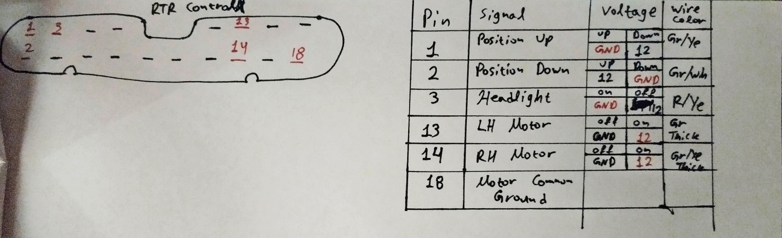
Connecting it to the car meant reverse-engineering the original connector. Multimeter, power probe, and common sense: the thick wires land on the output relays, so those are the motor feeds. The rest fell into place once I traced them against the diagram and the board.
Why it still misbehaves
First attempts to drive both motors from the custom board left the previously faulty side lagging. Up/down position still depends on sensing that the original RTR was doing, and my board wasn’t fully in that loop yet.
I tried to fake a motor for the RTR by putting a resistor between the RTR relay side and ground, hoping the logic circuit would see a completed path and behave. I measured the real motor resistance between the green and white/black wires to pick a value. Resistor emulation didn’t work.
Code versions since then have been a mix of almost working: lamps out of sync, continuous motion that never settles, or a tight loop of deploy/retract forever. Good enough to prove the hardware works, not ready to leave installed.
Next try
I don’t own an oscilloscope, and I haven’t learned to use one properly yet, so I can’t cleanly watch the RTR’s position signals. Next idea: stop trying to infer those signals from outside and wire them into my board directly.
I’ll lift the position wires off the RTR PCB and land them on the custom board. Common, Up, and Down go to microcontroller IO: common as an output, Up and Down as inputs. At startup, set common high. High on Up means the lamp is up. High on Down means it’s down. Neither means it’s somewhere in between. That should give the ATtiny a real position state to work from.
It also means rewriting a fair chunk of the control code, and probably adding debounce capacitors so noise on those lines doesn’t look like a position change.
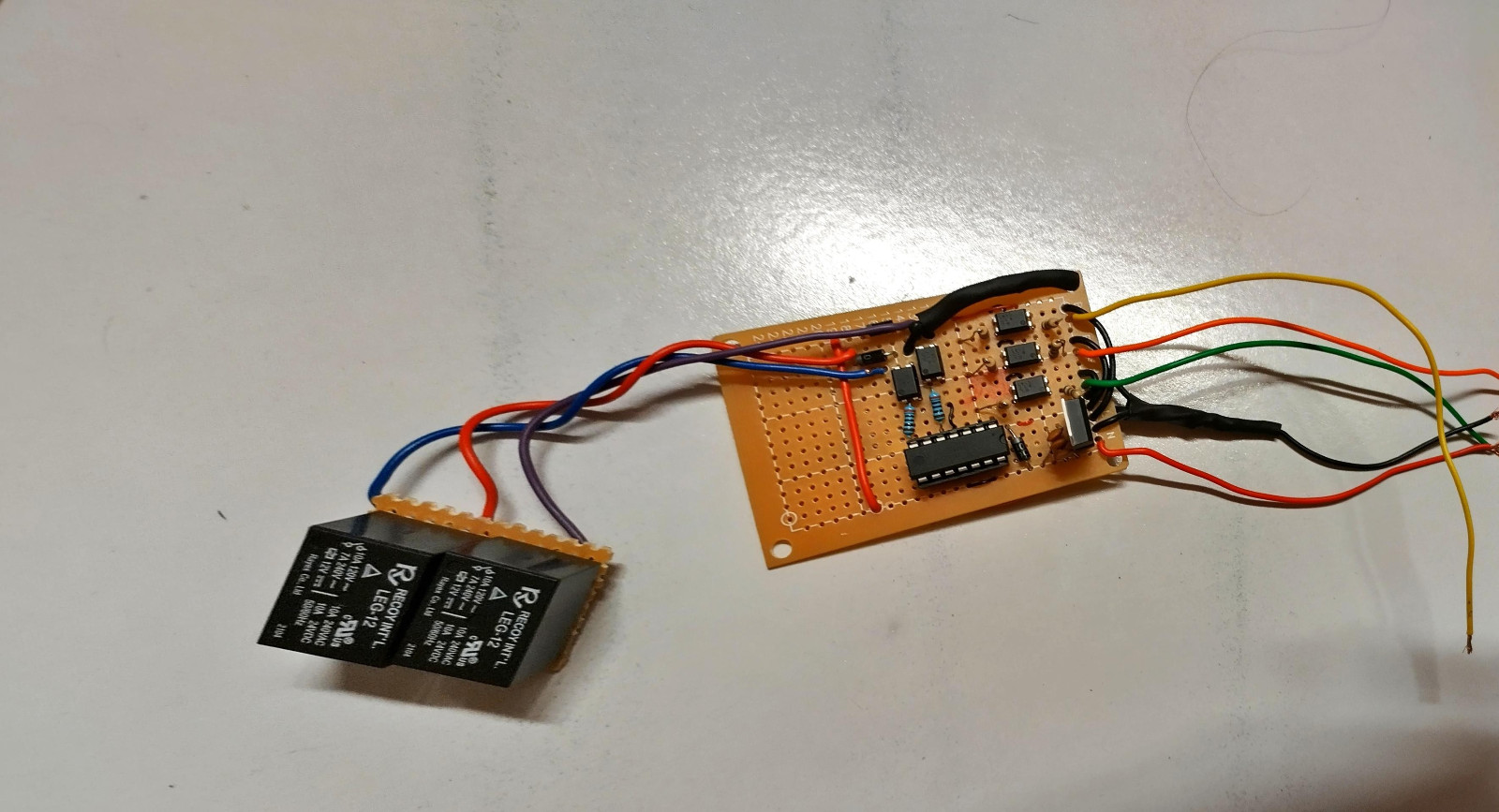
Board so far