Classic Car Manual -> Powerwindow Conversion
TLDR
My old power window kit kept failing on trips—windows stuck open or shut, no AC, no manual override—so I tore it out and went back to a crank. That worked, but I couldn’t adjust the window while driving solo. The original install was trash: speaker wire, oversized fuse, direct ignition power, cracked sheaths from bad cable angles, and sloppy mounting. I redid it right—used M4 rivnuts for solid mounting, proper gauge wires, crimped connections, heatshrink, a relay to isolate power, resettable fuse, and wrapped everything in fabric tape. The old DPDT switch system was too basic—no current sensing, so fuses popped if held too long. The new setup uses a control module with one-touch, current sensing via microcontroller and ADC, and a relay H-bridge to control motor direction. Switches now just signal the module. Transistors and flyback diodes safely handle relay control. Now it’s reliable, safe, and hands-free.
If you prefer videos over reading you can watch the video version Here
Problem
In the past I had the previous conversion break down on me while on several trips. The window got stuck open or closed with no way to lower it manually. The car has no AC and this happened mostly in summer trips. This made the car uncomfortable. One time I’ve had enough! I tore the door down on the side of the road and removed the powerwindow kit, reverting the window to crank operated.
After that a new problem appeared. While driving with the passenger, I could ask them to operate the crank for me, when driving alone i couldn’t make adjustments during the trip. It was either be uncofortable or crash.
Why the initial installation failed
Whoever installed this in the past clearly didn’t follow the instructions. The passenger door was like swiss cheese from mounting holes that didn’t end up being used. Also the angle of the chain cables was too steep wich ultimately led to the PTFE sheath cracking and allowing all kinds of road debris and moisture to enter the chain and bind it up.
Other than that, they drew power directly from the ignition. They also failed to use proper wires for the task. I found out they used speaker wire. The kit was hardwired and there was nothing that prevented the motor from drawing too much current other than a fuse. Don’t even get me started that the fuse was too large for the task, a whooping 20A fuse for something that drew tops 7-10A.
Doing it right
Other than the obvious safety things like choosing proper gauge wires and the appropriate fuse, there are a few things that can be improved.
Mounting
To mount the regulator side of the kit instead of drilling the door and using self tapping M3 screws, I opted to use M4 rivnuts. Self tapping screws loosen over time due to vibration. They loosen because they wear down the metal threads they have created as they vibrate from the car. At some pont (as in this case) they screws have loosened the threads to the point that they don’t hold the part down securely.
Why rivnuts? Rivnuts have several benefits:
- They offer more thread contact area improving the clamping force (compared to the 1-2 threads that screws can form in the thin sheet metal)
- They are easily replaceable if one fails (Overtorquing)
The only downside is that it takes a bit longer and needs more drilling operations depending on size. I had to drill 6mm holes insted of 3mm to install them. The benefit however is too significant to ignore
Wiring
The wiring side can be improved in several areas:
- Proper wire and fuse selection
- Crimp or solder the wires (Just twisting them together is a bad practice that I keep seeing on every vehicle I worked on so far and it needs to stop)
- Insulate properly with heatshrink (not just insulation tape, it tends to unwrap during high heat or over the years)
- Add an automotive relay to isolate the power windows from the battery (prevents battery drain)
- Add a resetable fuse in an easy to reach place that is rated below the actual fuse
- Wrap the entire complete harness with automotive grade, fabric tape to protect it form metal edges
If wanna go the extra mile buy some automotive wiring loom and it should be super protected.
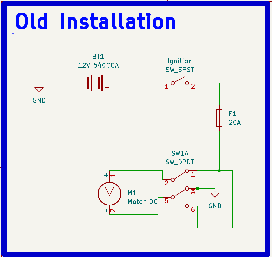
Wiring breakdown (Previous Installation)
The previous setup used a rather simple way to control the system. The system is comprised by A 5 pin switch, the wires and the motor itself. 12v and ground are fed to the switch and then 2 wires go to the motor. The switch is a DPDT (Double Pole Double Throw) - meaning it has 2 sets of contact and that they are independent of eachother - was used to send power to the motor from the ignition.
Basically power comes from the ignition to the switches NO (Normally Open) and Ground to the NC (Nomrally Closed). The Motor wires are connected to the COM (Common) sides of the switch. When the switch is not pressed no power makes it to the motor. When The switch is pressed down, 12V go to one motor lead and the other is grounded. When pressing the other way the contacts are reversed and the frist lead of the motor now is grounded and the second receives 12V, making the motor spin the other direction.
This is a simple reliable schematic. That is exactly the problem with it, it’s too simple. To operate it you have to hold down the switch till the window has reached the desired place - having your hand ocuppied like that is not very safe. Also if you hold too long the motor can no longer move the window and it starts to draw too many amps. After that the fuse pops and the system stops working and you are left without a window and a sudden urge to go fuse hunting- very convinient.
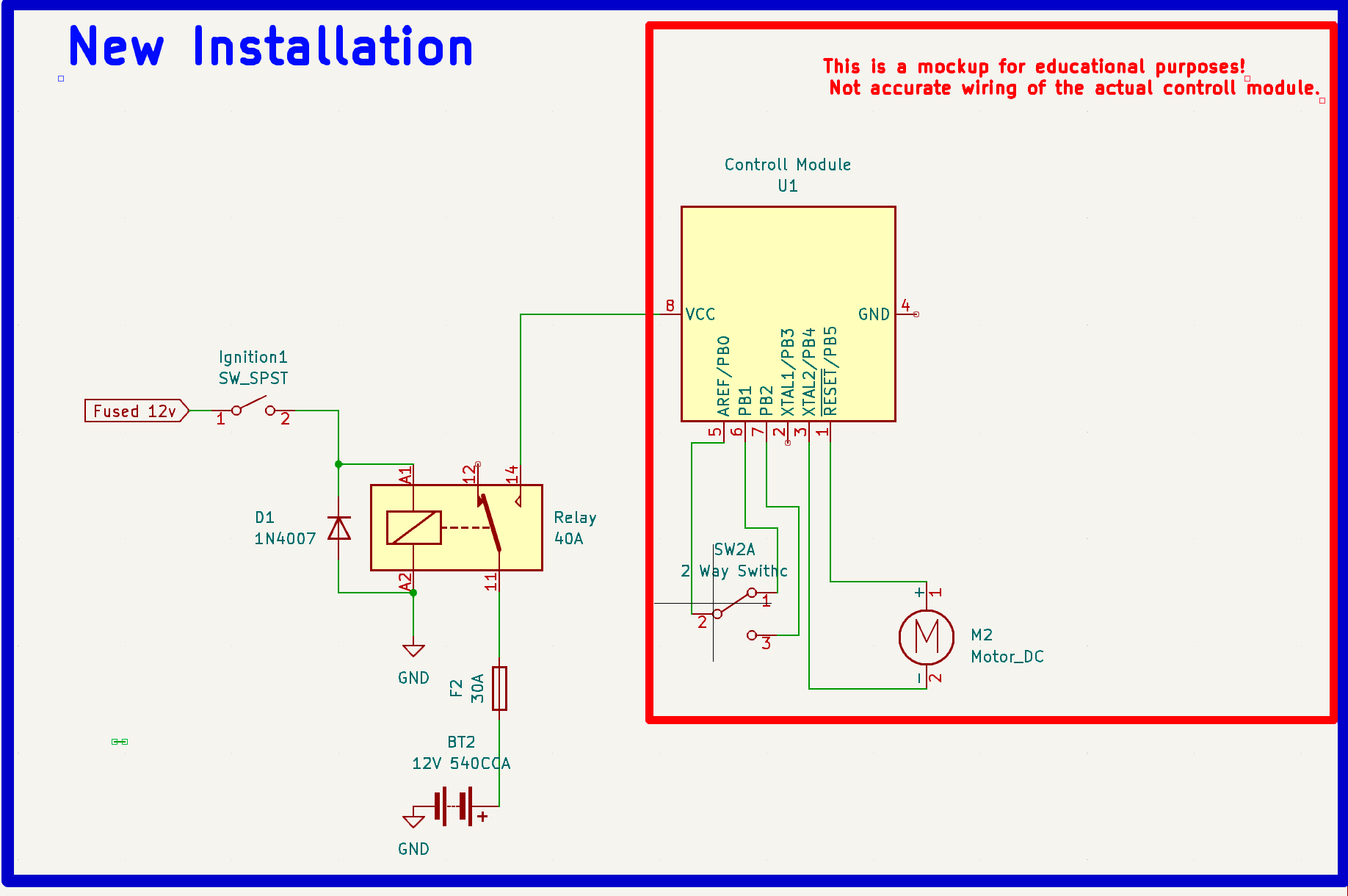
Wiring Breakdown (New Instlalation)
The new kit is several steps beyond previous solution. It came with a control module that handles the task for me. It has a built in, one touch functinallity along with auto window roll up upon lock (didn’t use that however).
The module allows the user to tweak the amperage the motor receives which is rather convinient if you like having intact fingers (although theres a saying in the field don’t put your fingers where you wouldn’t put your….. anyways).
The new switches are 4pin ones and they are SPDT. Whats different about them is that they are not used to handle the current themselves, but rather to signal to the control module what it should do with the windows.
The module takes the input from the switch and decides if it should move it up or down. If you are just trying to install the thing this is more than you need to know.
How does the module handle the task? What makes it tick?
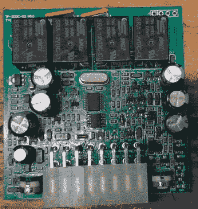
There is a microcontroller that decides based on some inputs.
- The most obvious one the switch press
- The motor current
For exaple the user presses the switch up. The microcotroler tries to move the window up. If the current it senses is bellow the stopping threshold then it sends power to the motor till the threshold is reached. Then it stops. If the window is already up then it tries to move it but the threshold is hit almost instantly and stops. This prevents destroying the motor and poping fuses unneccesarily.
But how does it sense it? For this module I’m not entirely sure, but I would guess it uses some ADC Converter (Analog to Digital) to convert current readings to voltage low enough to be sensed by a microcontroller (0-5V). The ADC matches the current reading to a voltage in that range. For instance if the max A it can hadle is 10A, 0V is well 0A, 5V is 10A and anything in between is interpreted accordingly.
Ok cool, but how does it send power to the motors? The siimple switch does it by flipping contacts how does the module do it?
The pricipal is similar but the implementation is different. In a nutshell a relay H-bridge is used. An H bridge in electronics refers to a specific component arangement. Modules like these typically use one of two systems to achieve this:
- A power relay and a direction relay per side. One is responsible for enabling power transmision to the motor. The other is responsible for switching the contacts to reverse the motor directin.
- An H bridge like arangement is used to selctively send power to the motor leads in the right polarity
This module used an H bridge configuration. In the diagram bellow you can see that if we selctively activate the relays we can both energize the motor and control its polarity. If no relay is switched the motor receives 12v or ground on both sides. This means no electrons flow and it just chills there. When one relay is activated then one lead receives 12v and the other is grounded. If the other one is also activated again nothing. If just the other one is activated then the power is reversed and the motor spins the other direction.
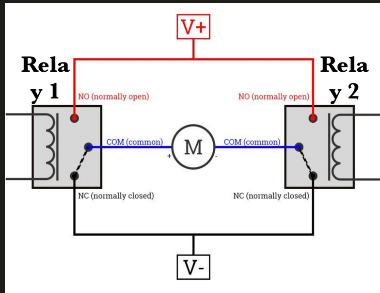
Important note! Automotive relays are 12V activated. That means that the relay coil is energized properly at 12V. Anything bellow 9V does not trigger the contacts. A microcontroller is used to make decisions. The problem is microcontrollers use logic level voltages (3.3 or 5V). A microcontroller cannot activate the relay (and would happily fry itself if we let it try). To solve this problem we use transistors. The microcontroller feeds the gate of the transistor using an apropriate saturation resistor to trigger it’s gate effectively. Then the transistor completes the realy coil circuit by grounding one side of it. The other side receives 12V constantly. This triggers the realy on. There is a huge ristk if the circuit was left like that. Sure it will work but eventually the transistors would be fried. Why is that you may ask. Relays have a coil. Coils resist the flow of electricity. They resist elctrons entering them but they also resist letting them go onece theyve made it in there. When power is cut off the coil has energy stored in it in the form of electric field. This energy is held there until the coil “decides” to let it go, all at once. This results in a huge boltage spike that can ruin electronics. To prevent this, a simple diode is connected in paralel to the coil that serves as a safe coil disscharge pathway. This is commonly reffered to as flyback diode.
3D Printing time
I designed this panel in fusion 360. The design is one of the simplest I’ve designed. I modeled a rectangle shape and the general shape of one of the switches. Then I used the switches as a tool to perform a cut on the rectangle shape. For the coin sorter I just measured the part and cut a rectangle shape with the minimum dimension of the latches in its back. Finally I finished things off by creating the bolt holes, a lip for the switches to latch on, and rounding things off.
I trimmed the original part with a blade and a torch. I used some M3 heatset inserts so that I could attach the panel with M3 countersank screws later.
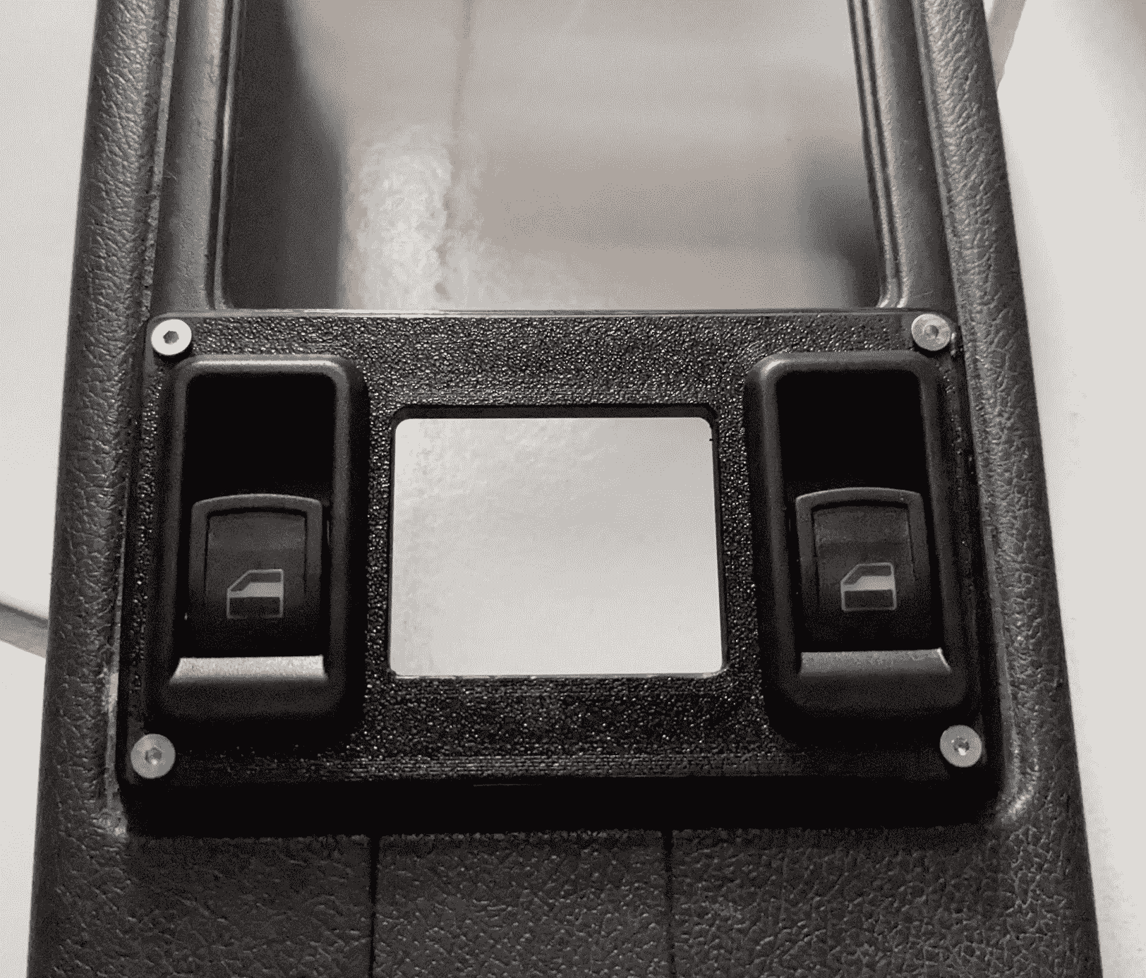
Here is the panel fitted to the center trim piece.
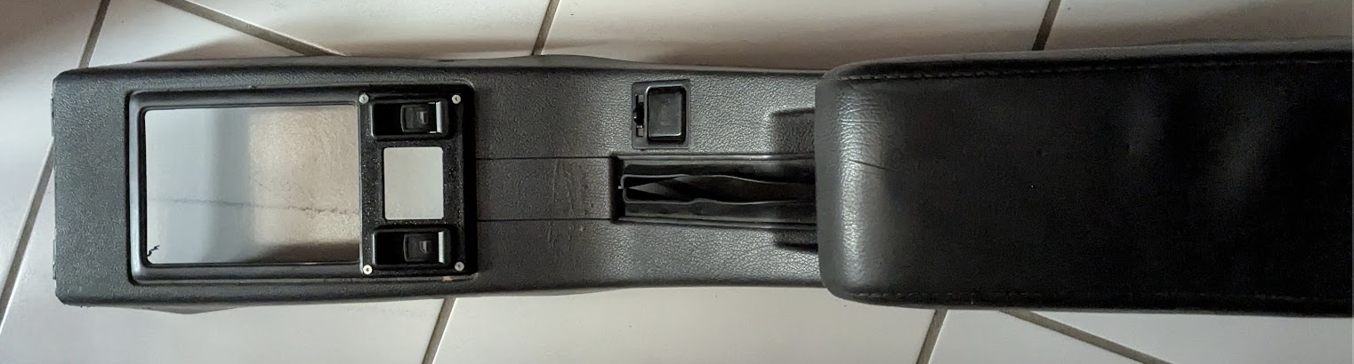
And from a closeup view.
First Summer Trip

A few days after installation, my partner, some friends and I went to Sifnos. We made extensive use of the system and it was a breeze to use! It came really handy while driving down the tiny roads of the island. Although skeptical at fist, I quickly became a big fan of the one touch function. I just pressed down once, and the window would do its thing, while I kept my eyes on the road, and hands where they should.